How to Replace the Controllers on your Grizzly V3Updated 9 months ago
Ariel Rider Grizzly V3 Controller Replacement
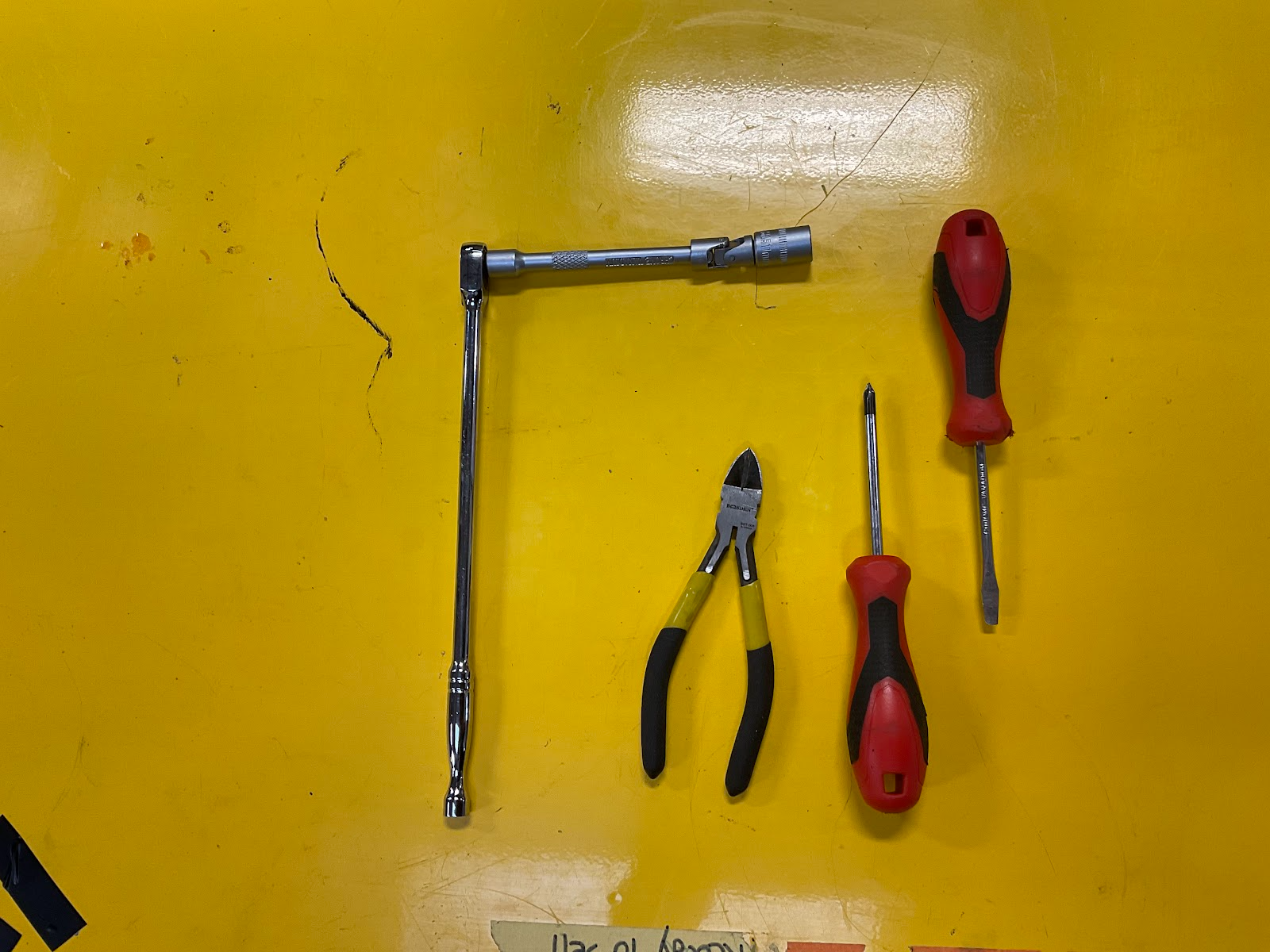
Tools required:
10mm Socket and Extension
Flush Cutters
Flathead and Phillips Head Screwdriver
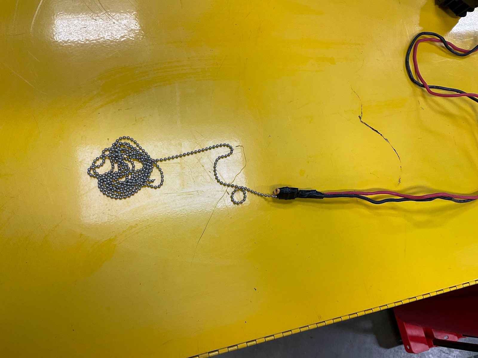
Fishing Line (SEE TIP)
DON’T SKIP!
!! THE FOLLOWING BEST PRACTICES ARE IMPORTANT !!
BEFORE DOING ANYTHING ELSE, REMOVE BOTH BATTERIES FROM THE BIKE AND THEN HOLD DOWN THE BIKE POWER BUTTON FOR 5 SECONDS. This dissipates any residual power in the system to prevent damage to components when connecting everything. This isn’t a safety precaution, component damage from residual power is a common occurrence when plugging in and unplugging components, even when the bike is turned off.
DO NOT SKIP THIS STEP.
CAUTION: The wires in the control box, especially the smaller wires of the battery detection module can be quite small and easily broken under strain. Be mindful of this when trying to fit everything into the control box. Avoid sharp bending or kinking of the cables in order to make things fit. When possible, push any excess cable into the frame so there is as much space inside the control box as possible.
NOTICE: Before you disconnect anything, it is a good idea to mark each motor cable as “F” or “R”, so they don’t get mixed up. Each controller has an F or R on the label indicating which controller it is. (See Figure 4)
FINAL WORD OF CAUTION: Use care with all the round connections when pulling them apart especially when plugging them in. They must be aligned properly before connecting. There is an arrow mark on the side of each connector that must be lined up BEFORE you attempt to push them together. The pins of the connections are easily bent. If this happens, all your efforts will be rewarded with a non-working bike. So, use extreme care with these connectors and double-check their alignment before connecting them.
The controllers are located under the saddle (seat). The saddle is held on by four nuts on the underside. The control box that houses all the wiring has a lid that is held on by two screws on the underside of the box. (See figures 1 & 2) Once the seat is removed you will see the controllers are held down by a bracket and nut. Remove this bracket and set it aside.
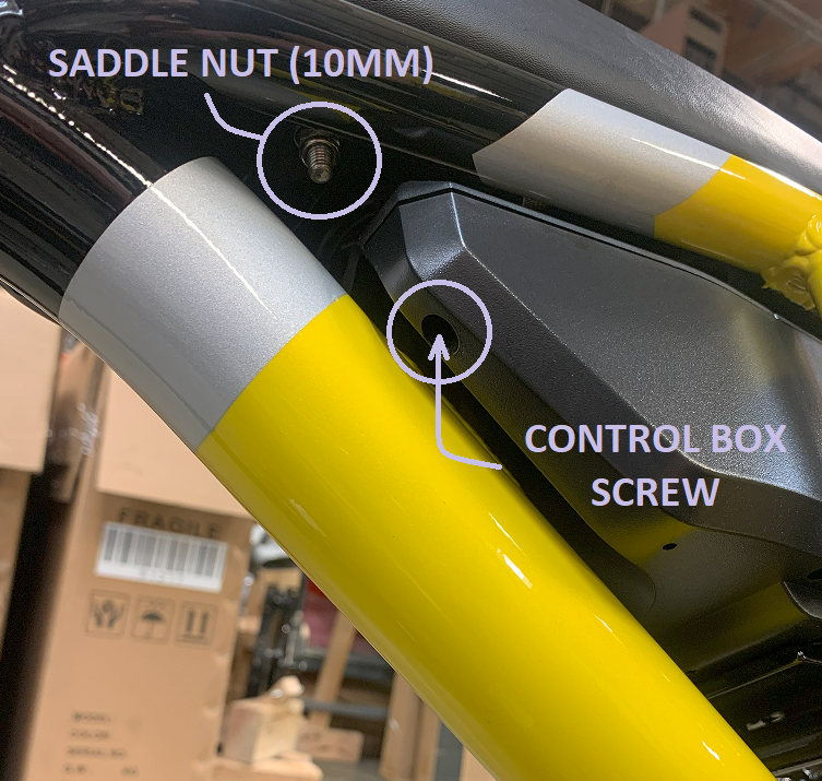
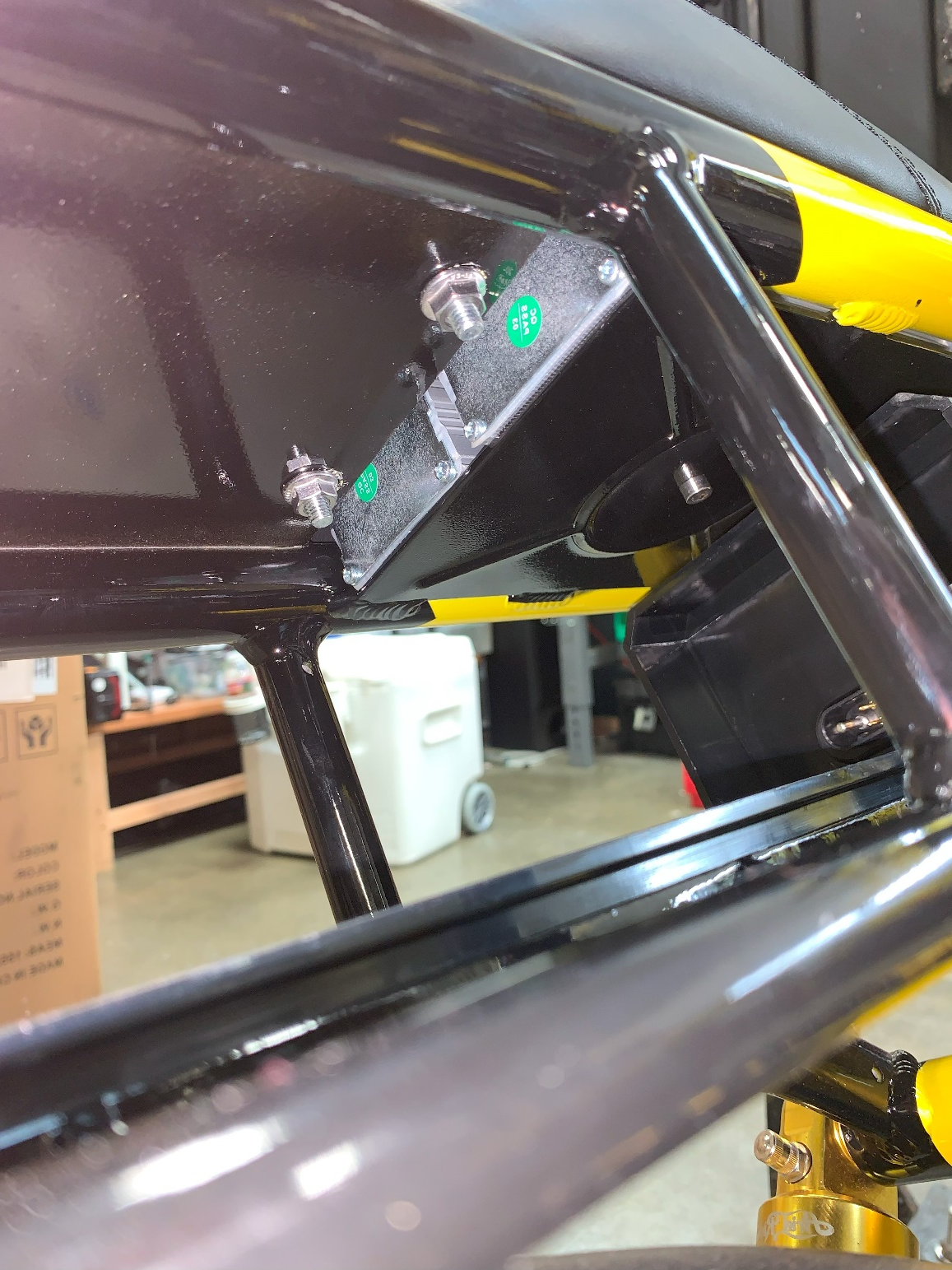
Figure 1. Figure 2.
NOTE: The smaller square connectors each have a retaining latch that must be pushed down to pull them apart (Figure 3). The motor cable has a metal retaining ring that must be turned (unscrewed) to disconnect.
Disconnect the power connections (Yellow).
Pull apart the smaller round connectors. DO NOT TWIST THEM, rock them gently without twisting if they are difficult to separate. They are a tight fit.
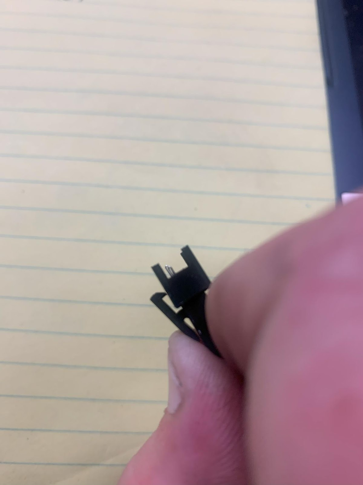
Figure 3.
In this guide, connections to the controllers are marked in the photos with blue and yellow tape for clarity. Blue tape is used with the #1 REAR controller, yellow tape is for the #2 FRONT.
The easiest way to identify your controllers is to look for the “R” or “F” on the label (Figure 4).
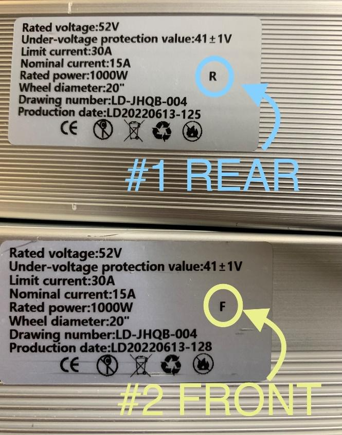
Figure 4.
Mark the motor connectors to indicate which controller they connect to.
You can now carefully disconnect everything and remove the controllers.
Each controller has a motor cable and power cable. In addition, #1 REAR has 6 smaller connections and #2 FRONT has 2 smaller connections. (See Figure 5)
Place the controllers side-by-side on the bike frame where the old controllers were and secure them with the clamping bracket. The controllers should be installed with the labels facing up with #1 REAR on the same side of the bike as the bike chain.
The two largest cables with the metal rings are for the motors. For now, push these off to the side and out of the way. These motor cables will be the very last cables that are connected.
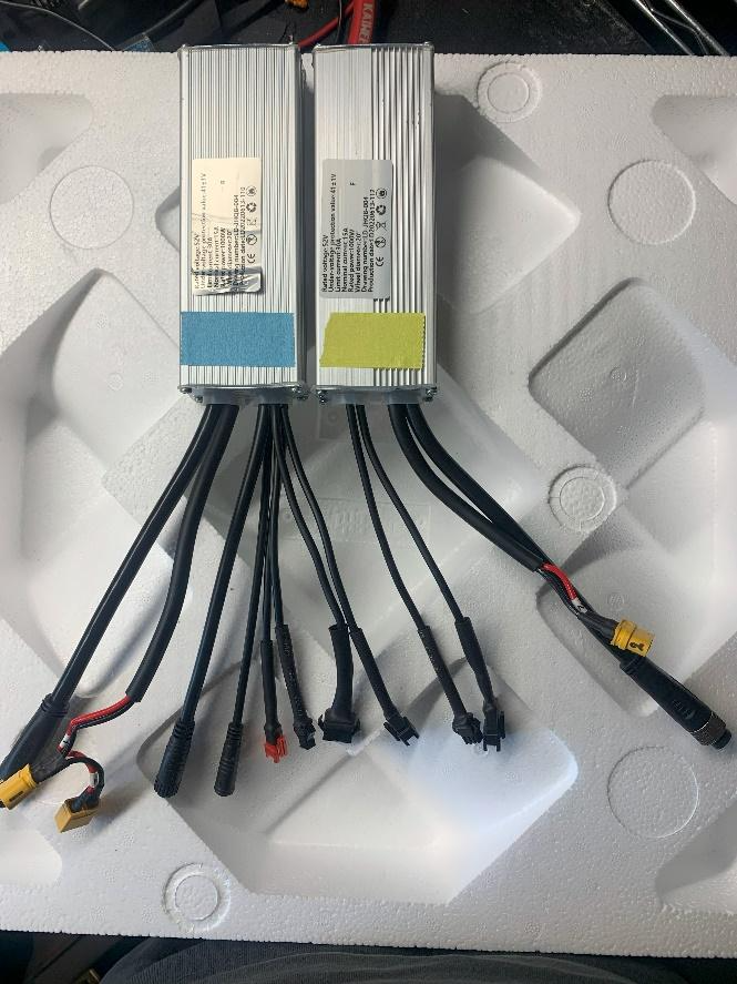
Figure 5.
Locate the 2-pin male connector on #1 REAR which is BLACK. (Figure 6) Tape this connector off and out of the way. It is not used and can cause damage if connected to anything.
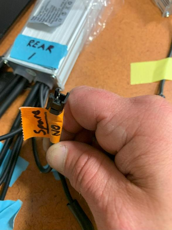
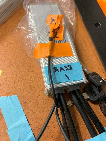
Figure 6. Figure 7.
Connect the red 2-pin male connector on #1 REAR to the taillight connector on the battery tray. (Figure 8 & 9) This connector can be found under the battery combiner. Figure 8 shows a battery tray with the battery combiner removed. The yellow XT connector is the rear battery power connection (labeled “3” on the white tag) and the taillight connector (seen at the top of figure 8) is a black 2-pin female connector.
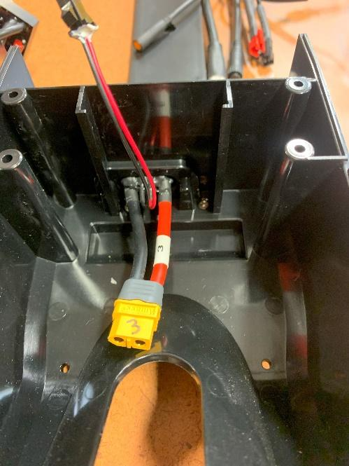
Figure 8. Figure 9.
All power connectors of the combiner (Figure 10), battery tray cables, and controllers have white numbered tags to identify them. Each numbered tag on the combiner matches a numbered tag on the battery tray connectors, controllers, etc.
NOTE: The combiner tags are labeled 1, 3, and 4. 3 is the rear battery tray, 4 is the front battery tray, and 1 goes to #1 REAR. (#2 FRONT gets power through an extra connector on the #1 REAR power cable) Match the numbers when making the power connections.
Connect the rear battery #3 first and tuck it underneath the combiner sitting it in the recess. (Figure 10) Then move to the next step before connecting the others.
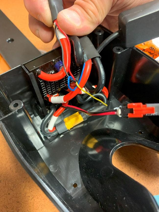
Figure 10.
The small wires that are connected to each power lead of the combiner are for the battery detection module. (Figure 11) It has a 2-pin male connector that connects to #1 REAR. (Figure 12) The combiner should be tucked into the corner of the tray (Figure 13). With the module in place, connect the 2-pin male connector to the 2-pin female on #1 REAR.
NOTE: It is important that the small wires of the detection module (or any other wires) are not under strain or being pulled upon, as breakage can occur. It may be necessary to temporarily unplug connections while situating the detection module so that none of the wires are being pulled on.
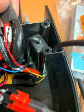
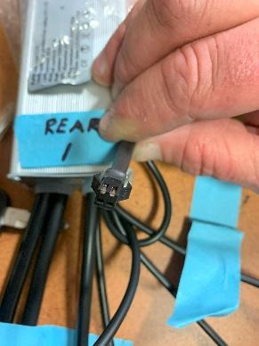
Figure 13. Figure 14.
With the detection module situated, the other power connections can be made. Connect #4 to the Front/Downtube battery tray, and then finally connect the controller power connectors together before plugging them into the combiner’s #1 connector.
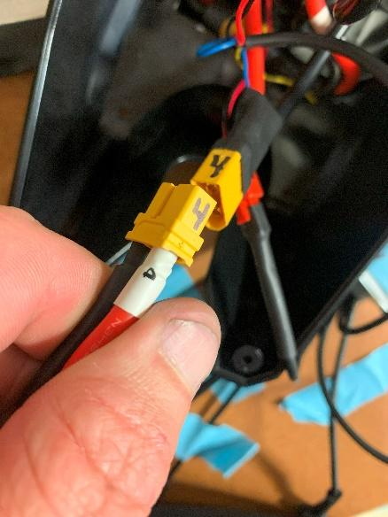
Figure 14.
The power wires can now be tucked away into the back of the box. (Figure 15) Use care to not stress the detection module wires.
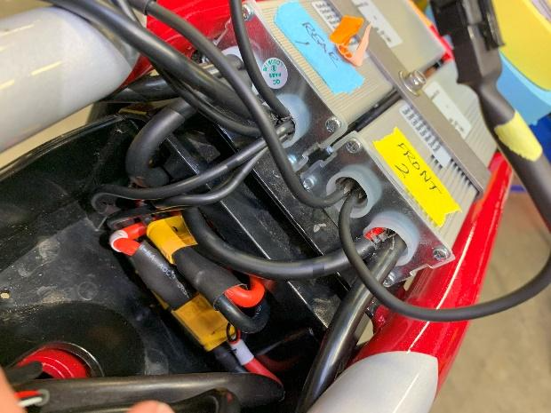
Figure 15.
The spare/unused connector wire that you taped out of the way earlier can also be tucked away into the back of the box leaving plenty of room for the remaining connections.
There are two 4-pin connectors on the controllers that are connected to each other. They are for controller communication. Connect them. (Figure 17)
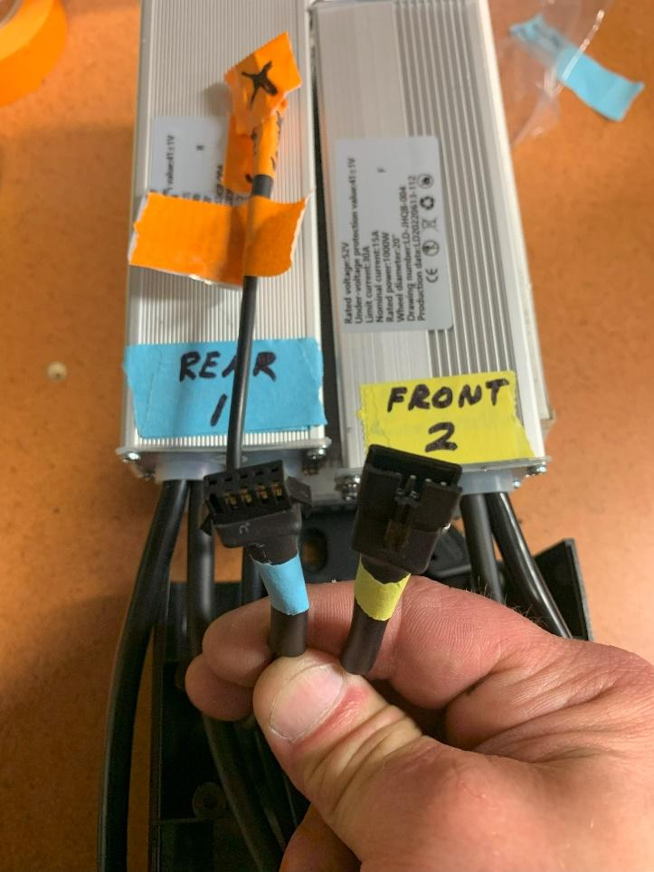
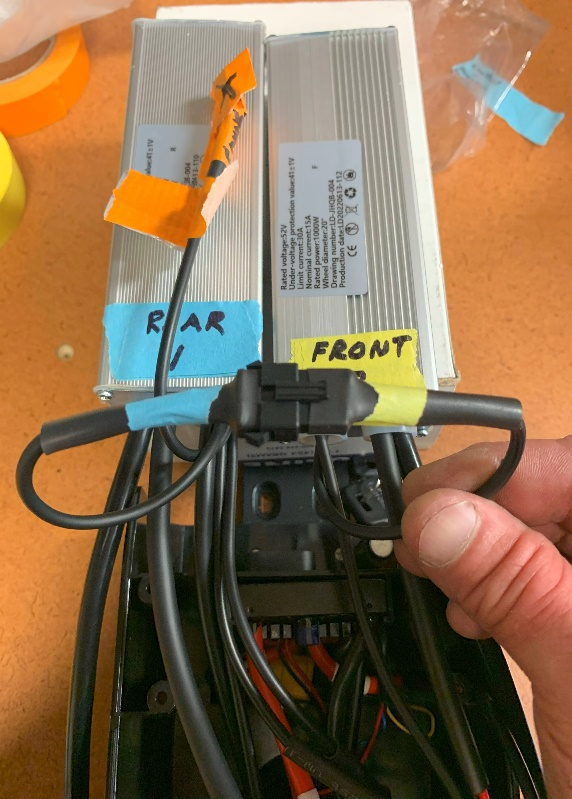
Figure 16. Figure 17.
Now all that is remaining are these three connections plus the motor connections. (Figure 18)
The 10-pin tree cable (main harness), and the orange 3-pin connector both connect to #1 REAR. Connect them.
The 3-pin square connector goes to the motor selector switch and connects to #2 FRONT. Connect it.
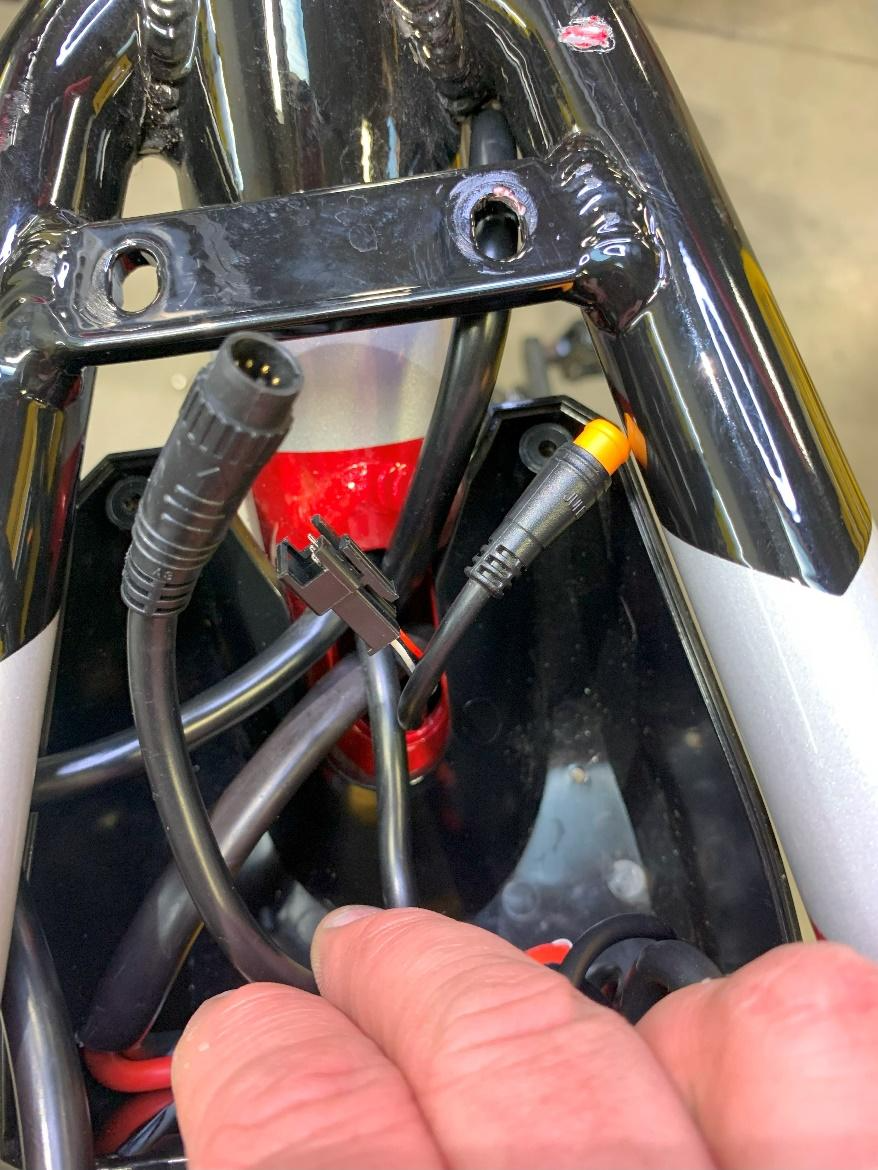
Figure 18.
The motor cables are the last connections to be made but they won’t be connected until after the lid is in place. But first, verify that the motor cables are marked correctly by determining which way they run inside the frame. The rear motor cable runs downward, and the front motor cable runs toward the front. Untangle them from the other cables and each other and check the direction they run (Figure 19).
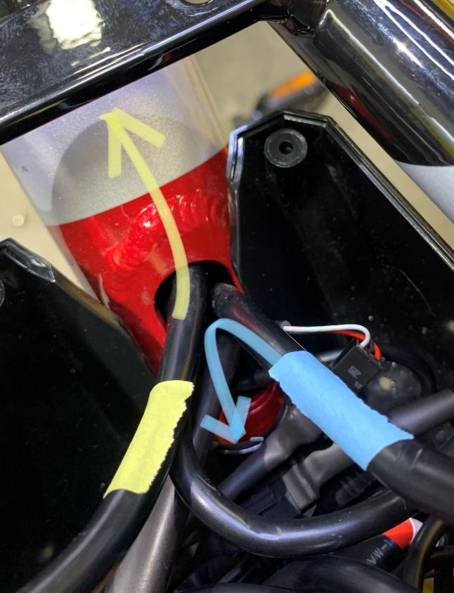
Figure 19.
Also, arrange the motor cables like shown so that the motor cables exit the lid on the opposite side of the controller it connects to. This will help prevent having to kink the cables to make the connections (Figure 20). Now install the lid.
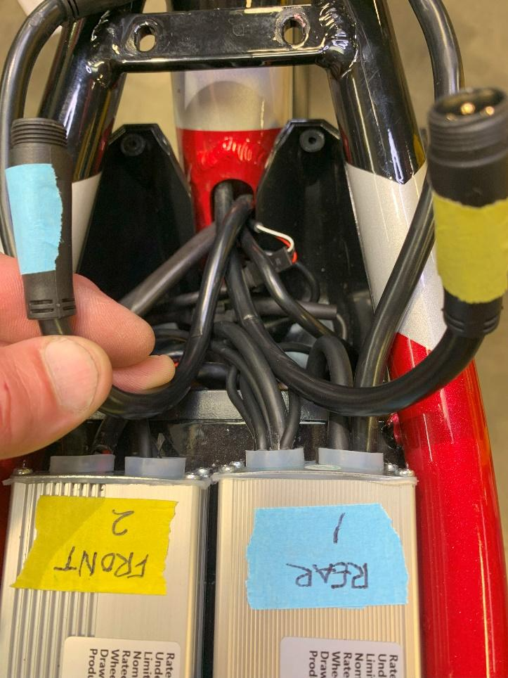
Figure 20.
Finally, connect the motor cables to their respective controllers without kinking the cables. Use a pair of Zip ties to hold them in place. Make sure that they fit neatly within this area and that they do not extend into the seat bolt area. Also, ensure that the cables are not pinched between the seat and the frame when installing the seat. This is how it should look when you have connected everything. No kinked cables, and nice and easy bends on everything (Figure 21).
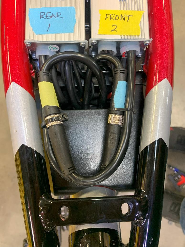
Figure 21.
Now make sure the hold-down bracket is secure and reinstall your saddle.
Before you put your batteries back in: Double check your wiring to your motors down by the axle and look over the headlight and control wiring carefully. If anything looks damaged, contact Ariel Rider support before powering up the bike. You don’t want to have to do this all over again. If everything looks ok, check that your batteries are turned off before installing them on the bike.
TIP: here are a few examples of good fishing lines:
Westinghouse house chain.