Installing the main wire harness on the 60V X-ClassUpdated a month ago
Overview
This guide will walk you through replacing your e-bike's main wire harness assembly. This is an advanced repair that requires careful attention to safety and proper procedures.
If you are uncomfortable performing this repair please seek the help of a professional bike mechanic.
Tools Required
Essential Tools
- 5mm hex (Allen) wrench
- 4mm hex (Allen) wrench
- 2.5mm hex (Allen) wrench
- Small screwdriver for cover screws
- Side cutters for zip ties
- Pull line (string or fish tape)
- Electrical tape
- New zip ties
Optional Tools
- Blocks of wood or foam (if flipping bike upside down)
Safety Precautions
🛑 CRITICAL SAFETY STEPS - DO NOT SKIP
- Turn the bike completely OFF
- Remove both batteries from the bike
- If flipping the bike upside down, support the handlebars with protective blocks
Step 1: Access the Front Components
Remove Front Components
- Front fender: Remove completely (use as a parts tray to organize screws)
- Display unit: Disconnect but can leave hanging gently - no need to fully remove
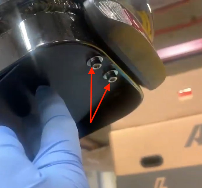
- Upper fairing mount: Remove 2 bolts (support the fairing while removing the second bolt)
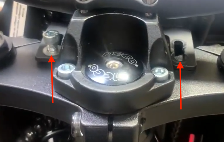
- Cut all wire wrap and zip ties that are bundling the front harness
- Unplug ALL harness connections at the front of the bike
Step 2: Access the Controller Bay
Remove Controller Cover
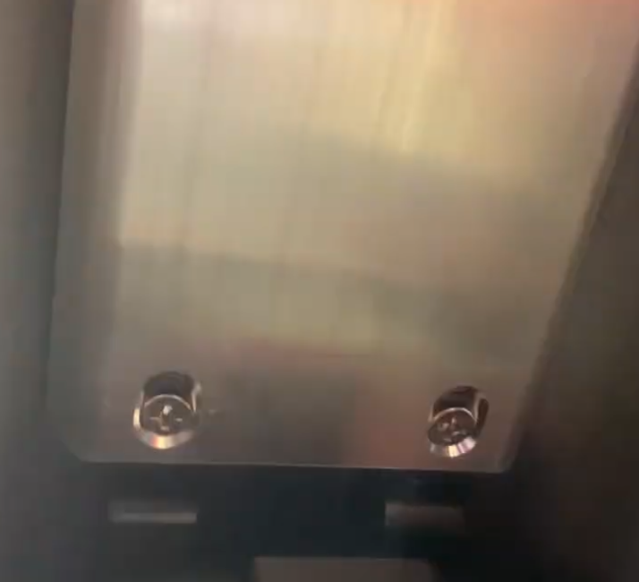
- Remove the 2 screws to expose the controller bay
- Cut zip ties holding the internal harness bundle
Remove Battery Latch Assembly
⚠️ Important: Follow this exact order to prevent parts from falling
- Remove 2 top screws at the plate
 Remove 2 screws at the opposite end
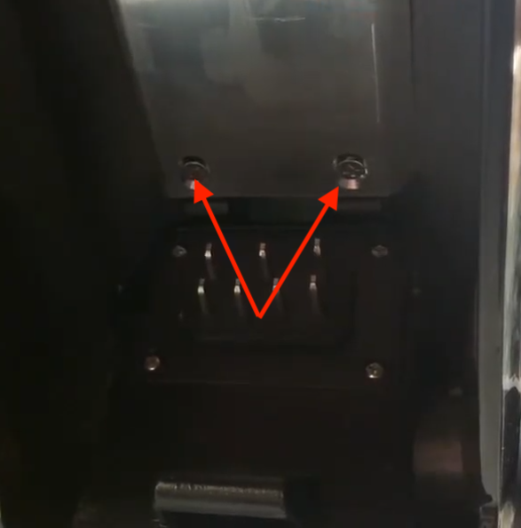
- Remove the plate first
- Then remove the 3 bottom frame screws
Pro Tip: Stuff paper towels in the battery mounting gaps so screws don't fall through the frame
Step 3: Locate and Disconnect Internal Connections
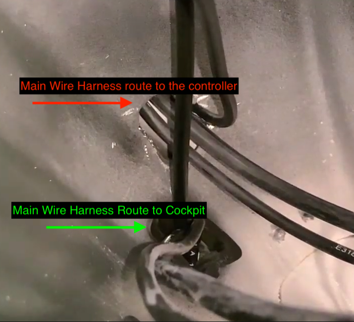
Understanding the Harness Path
The front harness cable enters at the rubber grommet → loops up through the internal guide tube → arrives in the controller bay
Identify Components in Controller Bay
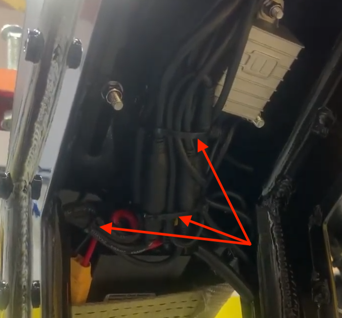
You'll see several connections. Here's what to disconnect and what to leave alone:
✅ DISCONNECT THESE ONLY: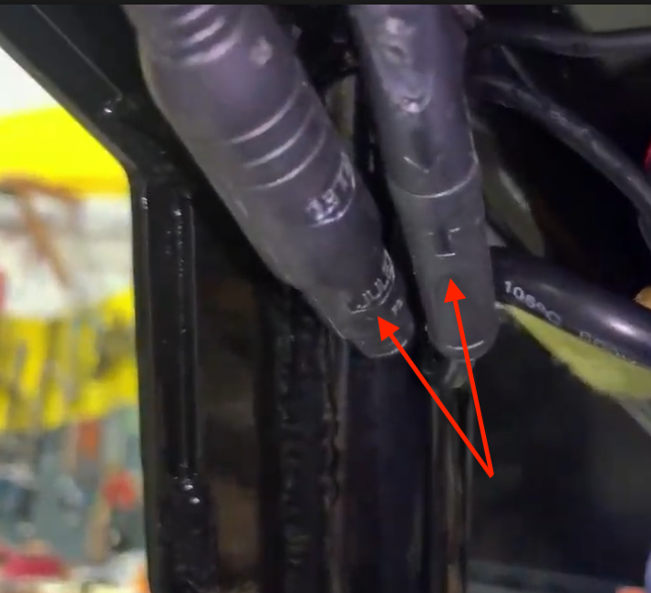
- 8-pin connector (black inside) going to controller
- 9-pin connector (black inside) going to controller
🚫 LEAVE THESE ALONE:
- Large power cable from main battery
- Auxiliary battery cable
- Blue plug to power switch
Step 4: Remove the Old Harness
Create a Pull Head
- Stagger the two disconnected plugs (don't bundle them into one large lump)
- Start wrapping electrical tape 2-3 inches past the connector ends
- Lay the pull string along the bundle, leaving a tail
- Fold the string tail back and tape over it (prevents slipping during pull)
- Add extra wraps at the edges for smooth pulling through the frame
Extract the Harness
- Feed the taped connectors into the frame opening from the controller bay
- Pull gently from the front of the battery compartment
- When the pull string appears in the battery compartment, immediately tie it to the frame near the swing arm (don't let it get pulled through!)
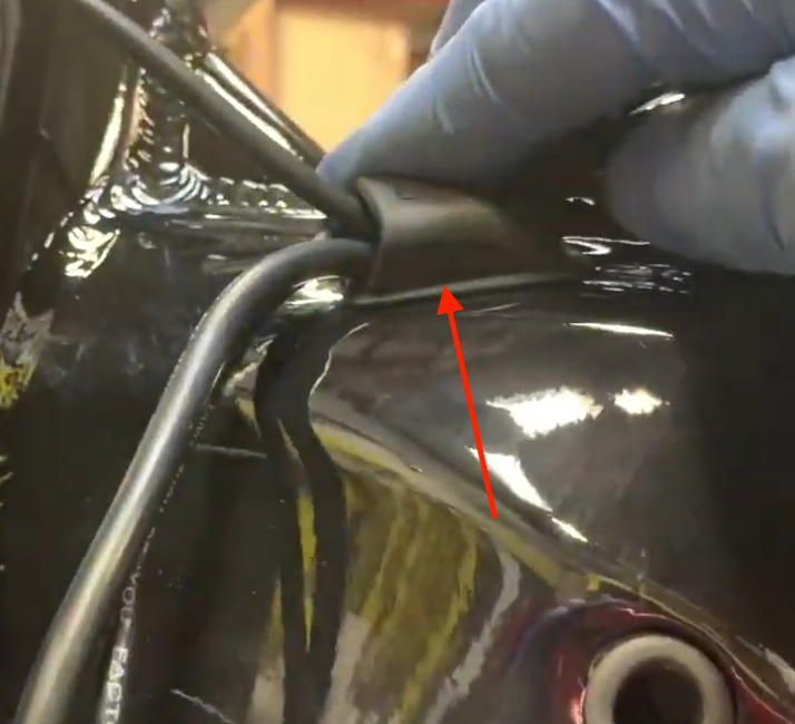
- Pop out the front grommet from the frame
- Pull the old harness completely out
Step 5: Install the New Harness
Prepare the New Harness
Attach the pull string to the new harness using the same technique (staggered connectors, smooth tape job, folded string tail)
Critical Routing Information
CRITICAL: The new harness must be fed through both the rubber grommet AND the internal guide tube - do NOT route it straight into the frame cavity
Pull Into Position
- Pull from the controller bay side using the string
- Guide from the front as needed to prevent binding
- Don't jerk the harness - ease it past corners and tight spots
Step 6: Reconnect All Components
At the Controller Bay
- Reconnect the 8-pin connector to the controller
- Reconnect the 9-pin connector to the controller
- Verify that auxiliary battery and blue power switch connections remain connected
- Reseat the front rubber grommet properly
- Secure with new zip ties (don't over-tighten)
At the Front of the Bike
- Switch assembly → reconnect at harness-side connector
- Left turn signal → connect to harness lead #2
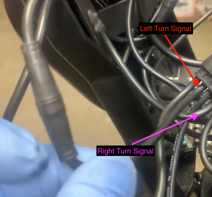
- Right turn signal → connect to harness lead #4
- Headlight, horn, and display → reconnect all connections
Step 7: Reassemble and Test
Reassembly Process
- Re-wrap the front harness with zip ties (leave enough loop for full steering sweep)
- Reinstall the upper fairing (2 bolts)
- Reinstall the display and front fender
- Reinstall the battery latch assembly and plate
- Reinstall the controller cover
Final Testing and Verification
Mechanical Test
Steering test: Turn handlebars fully left and right - verify no binding or tension on cables
Electrical Tests
- Reinstall both batteries
- Power ON the bike
- Test the following components:
- Display functionality
- Headlight operation
- Horn operation
- Turn signals: Left = lead #2, Right = lead #4
- Check for error codes on the display
- Verify the rubber grommet is fully seated
Professional Tips
- Never lose the pull string - tie it off immediately when it appears in the controller bay
- Smooth tape job = smooth installation - add extra wraps at sharp edges to prevent snags
- Use the removed fender as a parts tray to keep screws organized
- If a connector stops hard during installation, back up and re-angle - never force it
- Take photos before disconnecting components to reference during reassembly
Troubleshooting
If you encounter issues:
- Double-check all connections match the original configuration
- Verify the harness is routed through both grommet and guide tube
- Ensure no wires are pinched during reassembly
- Test steering movement before final assembly
When to Seek Professional Help
Contact a qualified e-bike technician if you:
- Are uncomfortable with any step in this process
- Encounter unexpected resistance during harness routing
- Experience electrical issues after reassembly
- Notice any damaged components during disassembly
Need additional support? Contact our technical support team at [email protected] for assistance with this advanced repair procedure.