Kepler 52V 1.0 - Pre 2026: Self Diagnosis SOPUpdated a month ago
Step 1: Initial Power Check
Check the battery level indicator
Test headlight, tail light, and turn signal switches
Verify tail light and turn signals are working
Step 2: Power Down Sequence
Hold the power button to turn the bike off
Remove battery
Hold the power button again to dissipate the remaining power in the controller (Power Cycle)
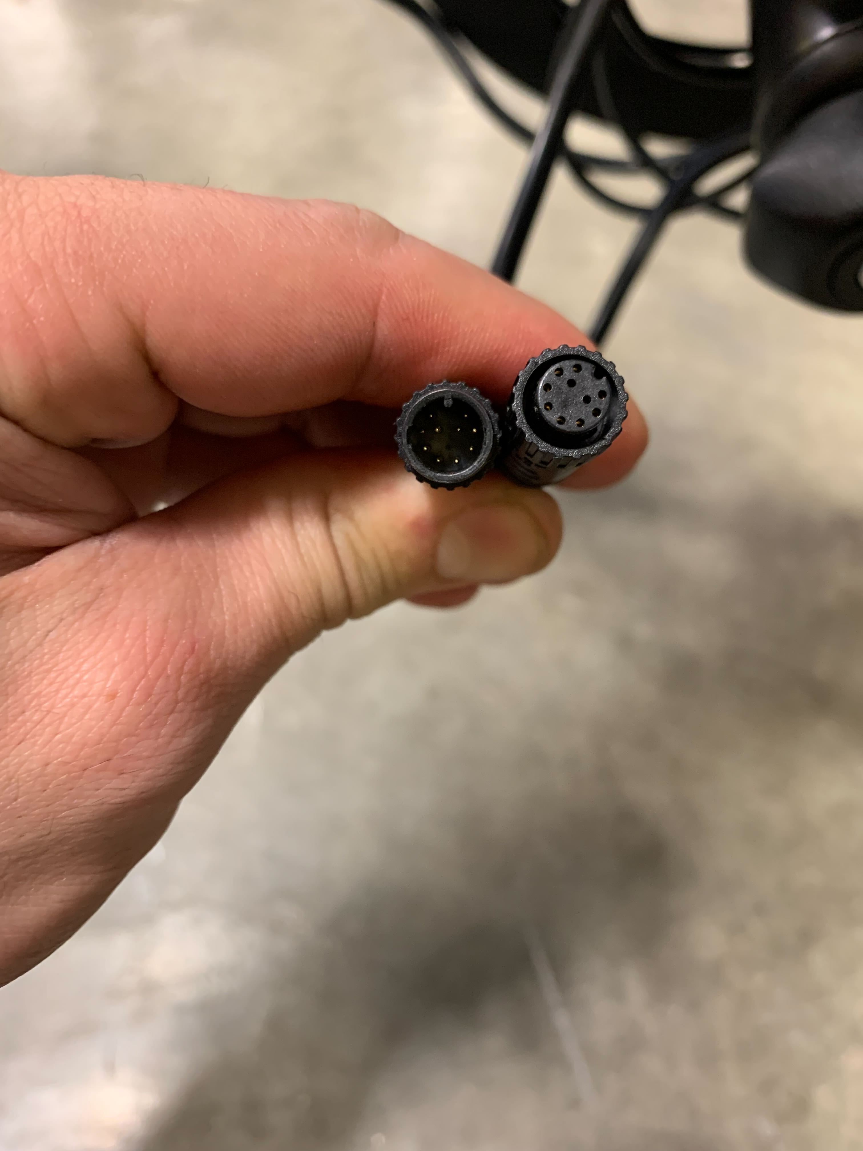
Step 3: Connector Inspection
Disconnect connectors one at a time
Inspect pins and seating
Note any burnt, broken, or bent pins and take photos for the tech agent
Remove display cable (pull straight out, do not twist)
Document any bent pins in the display connector
Step 4: Cable Access
Cut zip ties securing cables to the frame
Remove the grommet from under the bottom bracket
Pull out connectors seated in the frame
Inspect exposed connectors for condition
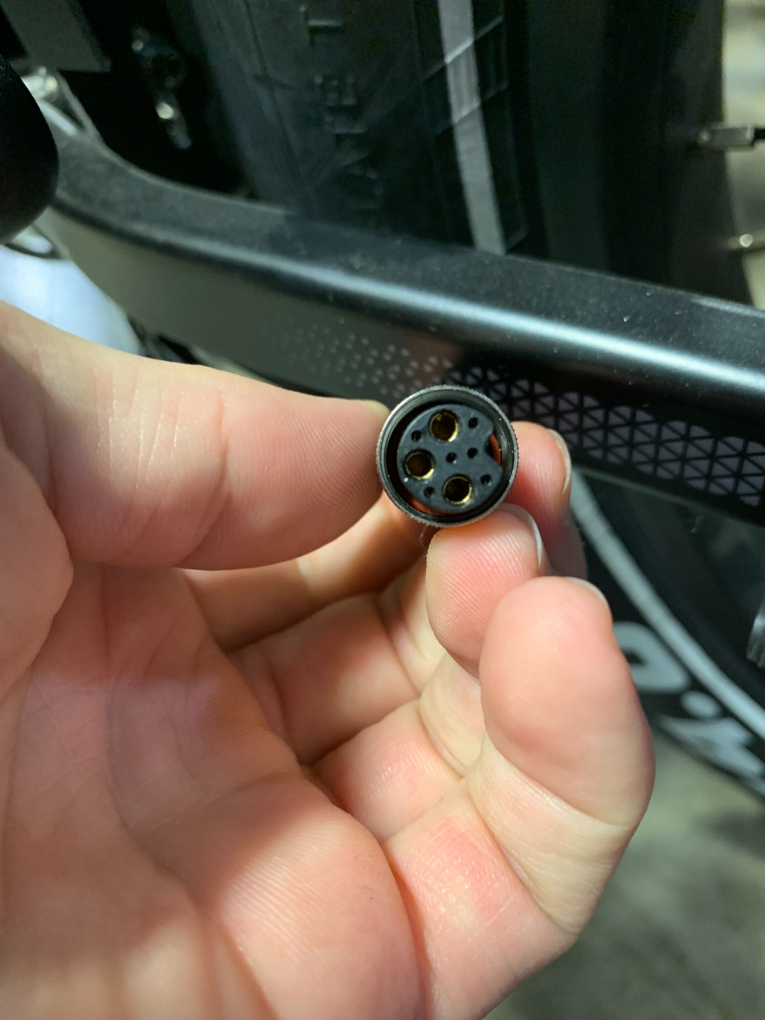
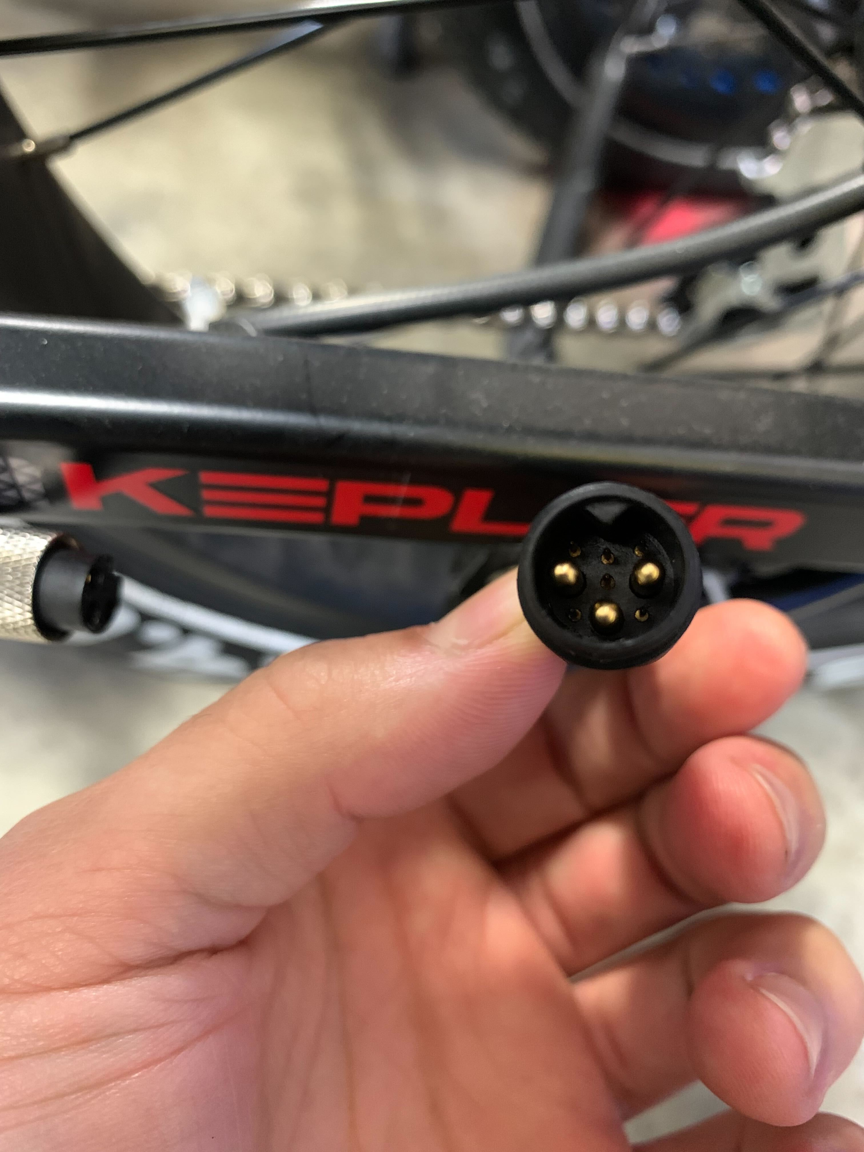
Step 5: Main Harness (Tree Cable) and Controller Check
Examine the main harness (Tree Cable) connector. This is a 10-pin connection.
Note any misaligned, bent, or displaced pins
Disconnect all controller connectors
Inspect controller connections
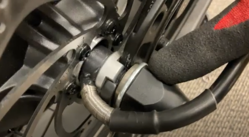
Step 6: Motor Cable Inspection
Unscrew the barrel connecting the motor cable to the controller cable
Check for burnt pins
Inspect the motor cable where it exits the motor hub for any damage
Step 7: Factory Reset
Hold the power button while turning the bike on until the password screen appears
Enter a password
Use plus/minus buttons to scroll through numbers
Use the power button to accept
Scroll to factory reset
Select yes to reset
Please exercise EXTREME caution to not short-circuit the battery. This can happen if you touch the two voltmeter leads together while getting a reading from the battery. Please ensure that while getting a reading from the battery, the two voltmeter leads DO NOT touch.
Remove the lower battery tray, and insert it on the removed battery.
Test the voltage at the Yellow XT90 connection
Step 8: Documentation
Record all findings for tech support agents